Foundation Course Electrical Theory Notes

Welcome to the Radio and Electronics theory Section of the course. This section is longer than some of the others, because there are several specifics that need to be covered. Look through the Syllabus document to see how the content is broken down. We will, on this page, try to go through each sub-clause in Section 3 of the Syllabus, Technical basics, one at a time.

As a consequrnnce of the level of detail, there are also extra questions in the Quiz. Have fun getting them all correct!

3.1 Units of measurement, abbreviations...

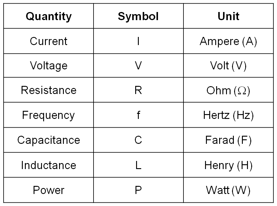
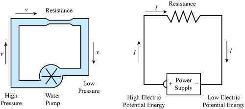
The units of measure for Voltage, Current, Resistance and Power require a basic understanding of the quantities themselves, and a context, such as a circuit. A circuit is a number of components that are connected together using conductive materials (usually, copper wires). Voltage is the difference in electrical pressure between two points in a circuit. Voltage is measured in Volts, and has the Symbol V (or E, for Electromotive Force (e.m.f.)). The difference in charge encourages electrons (negatively charged sub-atomic particles) to move from one point to the other. E.M.F. is literally the force that moves electrons. The rate of movement of electrons is called Current. It is the flow of electrons. Current is measured in Amperes, and has the Symbol I. Resistance is the opposition to current. It limits the current in a circuit. Resistance is measured in Ohms, and has the Symbol R. Each of the quantities has an abbreviation for the Units in which it is measured. Those abbreviations are in the table shown, along with some other quantities that we will mention later.

Power is the rate at which work is done, where work is the conversion of one form of energy into another. In the context of a simple circuit, the work is the rate at which electrical energy is converted into heat energy. Why does this happern? To pull an electron out of its orbit around an atom, reqires a very small amount of energy. The difference in between the positive and negative electrical charges in the circuit, takes care of that. The electrical energy is consumed. The free electron can then migrate to an adjacent atom. When the electron drops into the orbit of this new atom, the same small amount of energy is released. It is radiated as heat.

Power is measured in Watts, and has the symbol P. Electrical parts have a power rating based on their limit in regard to the rate at which the energy conversion occurs.

The Power of a Radio Emission is also given in Watts.

Electrical Units

3.1 ...and multiple/sub-multiple prefixes

In physics (Yes, that's what this is all about) when using standard units, we measure very very large values and, sometimes, very very small values. Instead of having to write lots of zeros (eg. 0.00002 Amperes) we use multiples of the units or sub-multiples of them for very small amounts. You are already familiar with the idea. We don't refer to large distances in metres. We use kilometres. 1 kilometre = 1000 metres. When measuring very small lengths or distances, we use millimetres rather than the base unit, metres. 1 mm = 1/1000 of a metre. Refernig back to the example, 0.00002 Amperes of current = 20 microAmperes. When doing calculations using multiples and sub-multiples of units, you have to be careful about the actual values in the base units, and convert things accordingly. Refer to the table shown to a basis on which to do those conversions. There are many examples of where we would use this idea in electronices.

Multiples and sub-multiples of units

3.2 Meaning of DC and AC

Direct current (DC) is a current in which the electron flow does not change direction. In a simple circuit with a battery as the voltage source, one battery terminal is called 'Positive', and the other is 'Negative'. Current is said to flow from positive to negative. In a circuit with an Alternating current (AC) voltage source, the flow of electrons changes direction as the voltage changes. Current flow is like water flow in a hydrolic system or river. See how the water flow analogy is used in the animation to the right. These images describe the difference between DC and AC.

Most peices of electronic equipment, including radio transceivers, need a DC supply. In the case of a transceiver it is typically a 13.8 Volt supply. Appliances that plug into a power point, such as heaters, vacuum cleaners and toasters, need an AC supply. In Australia, the AC voltage available at a power point is 230 Volts.

AC supplies have a sinewave shape. The frequency of the AC supply in Australia is 50 Hz. Other signals that are sinewaves of a specific frequency include the following:

DC water analogy AC water analogy

3.3 Audio and Radio Frequencies

Audio frequencies are the frequencies of the sound waves (compression waves) in the air, that vibrate our eardrums. Nominally, we can hear frequencies between 20 Hertz (20 cycles per second) and 20 kHertz (20,000 cycles per second). This set of values is only true before we have had an ear infection, suffered a blow to the side of the head or stood too close to the speakers at an AC-DC concert. Most stereo systems can only reproduce sounds between about 50 Hz and 16 kHz.

The audio frequencies used to transmit a voice signal over the radio or telephone are limited to a range of 300 Hz to 3 kHz. These are the frequencies neccessary for a human voice to be understood. To include more frequencies would increase the radio or data bandwidth required, and that would be inefficient.

Radio frequencies (The carrier frequencies of electromagnetic signals used for radiocommunications) cover a wide range. The radio spectrum includes a number of bands that can be described in the following terms:

Some applications for the different frequency bands, and information about the Wavelength, are described in the accompanying image.

The radio spectrum

3.4 The Meaning of AM and FM

The way in which an Information Signal is carried on a radio frequency carrier wave is by modulating the radio wave. That means that some aspect of the sinewave is manipulated in some way. The two major aspects of a sinewave are amplitude and frequency. The manipulation of either of these properties of the wave is called modulation.
Amplitude Modulation (AM) is where the size of the wave is modulated.
Frequency Modulation (FM) is where the frequency is changed slightly, in sympathy with the information signal (audio).
The animation to the right describes the difference between thw two types of modulation. Be aware that there is much more difference between the audio frequencies and the radio frequencies. Also, the change in frequency in FM is much more subtle than is shown in the animation. These properties were made more obvious for the sake of the animation.

The radio frequency carrier wave is modulated in the transmitter. When the transmission is received, the signal is Demodulated to extract the information. The audio frequencies are sent from the demodulator to an audio amplifier and a speaker.

Modulation animation